Motor Rotor Shaft CNC Machining
Product Overview
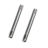
The Motor Rotor Shaft is a core rotating element in electric motors, serving as the main axis that connects the rotor to external mechanical components such as gears, pulleys, or couplings. This shaft not only transfers torque and rotational motion but also ensures the rotor stays centered and stable during high-speed operation.
CNC precision machining is used to manufacture rotor shafts with high accuracy, smooth surface finishes, and strict dimensional tolerances, making them suitable for a wide range of high-performance motor applications.
Key Features
High Dimensional Accuracy: Typical tolerances down to ±0.003 mm
Excellent Concentricity: Low radial runout for high-speed stability
Superior Surface Finish: Ra 0.2–0.4 μm for reduced friction and noise
High Tensile Strength & Fatigue Resistance
Balance-Ready: Designed for dynamic balancing in high RPM motors
Material Options: SUS303, SUS304, SUS316, 40Cr, S45C, titanium alloy, etc.
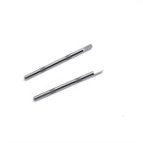
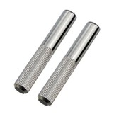
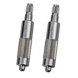
Custom Machining: Shaft ends can be milled, slotted, threaded, or grooved as per design requirements
Applications
Motor rotor shafts are widely used in:
DC & AC Motors (brushless, brushed, induction, servo motors)
Automotive Drive Motors (EV traction motors, HVAC blowers, wiper motors)
Industrial Automation (servo drives, CNC equipment, gear reducers)
Home Appliances (air conditioners, washing machines, vacuum cleaners)
Power Tools & Handheld Equipment
Medical Devices (surgical drills, ventilator drives)
Drone and UAV Motors
CNC Machining Process
Step 1: Material Preparation
Material selection depends on the motor's power, speed, and environment.
Common options:
SUS304 / SUS316 – corrosion-resistant
S45C / 40Cr – high strength
Titanium – lightweight and high strength
Brass / Aluminum – for miniature or low-load motors
Step 2: CNC Turning
High-precision CNC lathes shape the shaft body
Multi-axis CNC machines used for complex geometries and tight tolerances
Step 3: Centerless or Cylindrical Grinding
Achieves consistent outer diameter accuracy and smooth finish
Ensures tight shaft-to-bearing fit, reducing vibration
Step 4: End Machining
Threads, grooves, flat surfaces, holes, cross-pins, splines as per drawing
Achieved using CNC milling, slotting, drilling, or broaching
Step 5: Heat Treatment (if needed)
Induction hardening or quenching & tempering to enhance wear and fatigue resistance
Carburizing for surface hardness when required
Step 6: Surface Finishing
Surface treatment options include:
Hard chrome plating
Black oxide
Nickel plating
Passivation (for stainless steel)
Oil-coating or anti-rust film
Step 7: Inspection and Testing
Dimensional inspection using micrometers and CMM
Concentricity and runout testing (especially critical in high-speed motors)
Surface roughness and hardness testing
Optional: dynamic balancing for rotor assemblies
Advantages of Our CNC Machined Rotor Shafts
Over 16 years of shaft manufacturing experience
High-precision machining using Swiss-type lathes, CNC centers, and grinders
Full customization available for OEM/ODM motor assemblies
ISO9001-certified quality control
Exports to EU, USA, Southeast Asia, and Japan


Hot Tags: motor rotor shaft cnc machining, China motor rotor shaft cnc machining manufacturers, suppliers, factory